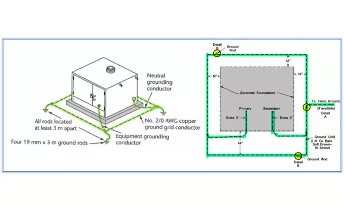
Transformer diagrams are essential tools for understanding the structure and working principles of transformers. They provide a visual representation of the components and connections within a transformer, making it easier to grasp how these devices transfer electrical energy between circuits. Whether you are an electrical engineer or a student learning about power systems, knowing how to read and interpret transformer diagrams is crucial.
Basic Components of a Transformer
Core
The core is the central part of a transformer and serves as the path for magnetic flux. It is typically made of laminated silicon steel sheets. These laminations help reduce eddy current losses, which occur when the alternating magnetic field induces currents within the core material. The core provides a low reluctance path for the magnetic flux, ensuring that the flux generated by the primary winding links effectively with the secondary winding.
Windings
A transformer consists of two or more windings: the primary winding and the secondary winding. The primary winding is connected to the input voltage source and generates the magnetic flux when an alternating current flows through it. The secondary winding is where the induced voltage is generated due to the changing magnetic flux. The number of turns in the primary and secondary windings determines the voltage transformation ratio. For example, if the secondary winding has more turns than the primary winding, the output voltage will be higher than the input voltage (step-up transformer). Conversely, if the secondary winding has fewer turns, the output voltage will be lower (step-down transformer).
Types of Transformers and Their Diagrams
Single-Phase Transformer Diagram
A single-phase transformer is the simplest type of transformer and consists of a single primary winding and a single secondary winding. The primary winding is connected to an alternating current (AC) voltage source, which generates a varying magnetic flux in the core. This flux induces a voltage in the secondary winding. The diagram of a single-phase transformer typically shows the primary and secondary windings wrapped around the core, with connections for the input and output voltages.
Three-Phase Transformer Diagram
Three-phase transformers are used in power systems to handle three-phase AC voltages. They can have different types of connections, such as star-star, delta-delta, star-delta, and delta-star. Each type of connection has its own advantages and is used for specific applications. The diagram of a three-phase transformer shows the three primary windings and three secondary windings connected in the desired configuration. The star connection has all three windings connected to a common neutral point, while the delta connection has the windings connected in a loop.
Step-Up and Step-Down Transformer Diagrams
Step-up and step-down transformers are designed to increase or decrease the voltage level, respectively. The diagram of a step-up transformer shows the secondary winding with more turns than the primary winding. This results in a higher output voltage compared to the input voltage. On the other hand, a step-down transformer has fewer turns in the secondary winding, leading to a lower output voltage. These diagrams help illustrate how the number of turns in the windings affects the voltage transformation.
Working Principle of Transformers
Electromagnetic Induction
The working principle of a transformer is based on Faraday’s Law of Electromagnetic Induction. When an alternating current flows through the primary winding, it creates a varying magnetic field in the core. This changing magnetic field induces an electromotive force (EMF) in the secondary winding. The magnitude of the induced EMF is proportional to the rate of change of the magnetic flux and the number of turns in the winding.
Mutual Induction
Mutual induction is the process by which a changing magnetic field in one coil induces a voltage in a nearby coil. In a transformer, the primary and secondary windings are magnetically coupled through the core. The varying magnetic flux generated by the primary winding links with the secondary winding, inducing a voltage in it. This mutual induction allows the transfer of electrical energy between the two windings without a direct electrical connection.
Turns Ratio
The turns ratio is the ratio of the number of turns in the primary winding to the number of turns in the secondary winding. It determines the voltage transformation ratio of the transformer. For example, if the turns ratio is 1:2, the secondary voltage will be twice the primary voltage (step-up transformer). Conversely, if the turns ratio is 2:1, the secondary voltage will be half the primary voltage (step-down transformer). The turns ratio is an important parameter in designing transformers for specific applications.
Importance of Transformer Diagrams
Transformer diagrams are essential for understanding the structure and working principles of transformers. They provide a visual representation of the components and connections, making it easier to grasp how transformers transfer electrical energy between circuits. These diagrams are particularly useful for students and engineers who need to design, analyze, and troubleshoot transformer-based systems. By studying transformer diagrams, one can gain insights into the voltage transformation process, the types of connections used, and the overall performance of the transformer.
Conclusion
Transformer diagrams are valuable tools for visualizing and understanding the working principles of transformers. They show the components such as the core and windings, and illustrate how these elements work together to transfer electrical energy. Whether it is a single-phase or three-phase transformer, or a step-up or step-down transformer, the diagrams provide a clear picture of the voltage transformation process. By mastering the interpretation of transformer diagrams, one can better design, analyze, and maintain transformer-based electrical systems.
Related Topics:

