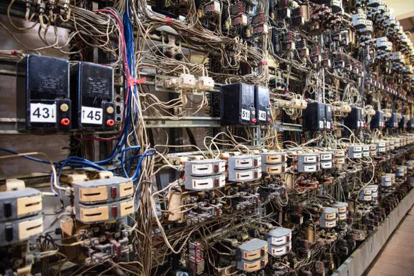
Current transformers (CTs) play a crucial role in the measurement and protection of electrical systems by transforming high currents into proportional, manageable currents for instruments and relays. Central to their operation are the primary (P1) and secondary (P2) windings, which are fundamental components determining their performance and application. This article delves into the functions, characteristics, and importance of P1 and P2 windings in current transformers.
Introduction to Current Transformers (CTs)
Current transformers are indispensable devices in electrical power systems, used primarily to step down high currents to levels suitable for measurement and protection equipment. They operate on the principle of electromagnetic induction and consist of two main parts: the primary winding (P1) and the secondary winding (P2).
Primary Winding (P1) in Current Transformers
The primary winding (P1) of a current transformer is where the current to be measured or monitored flows. It typically consists of one or more turns of thick conductor material, designed to withstand the high currents present in the circuit being monitored. P1 is wound around the core of the CT, which is often made of high-permeability material such as silicon steel or nickel-iron alloys. The core’s role is crucial as it enhances the magnetic coupling between the primary and secondary windings, ensuring accurate current transformation.
Characteristics of P1:
High Current Handling: P1 must handle the full load current of the circuit under measurement without saturating the core material. Saturation occurs when the magnetic flux in the core reaches its maximum limit, leading to inaccuracies in the CT’s output.
Turns Ratio: The number of turns in P1 determines the CT’s turns ratio, which defines the relationship between the primary current and the secondary current. This ratio is essential for scaling down the current to a level suitable for the secondary winding and connected instruments.
Insulation and Construction: Given its proximity to high currents, P1 is insulated and constructed robustly to withstand the electrical stresses and mechanical vibrations encountered in industrial environments.
Secondary Winding (P2) in Current Transformers
The secondary winding (P2) of a current transformer is where the transformed current is induced by electromagnetic induction. P2 typically consists of a large number of turns of fine wire compared to P1, wound around the same core material as the primary winding. This configuration allows for the creation of a secondary current that is proportional to the primary current but reduced in magnitude.
Characteristics of P2:
Current Transformation: P2 generates a secondary current that is a precise, scaled-down replica of the primary current. The turns ratio between P1 and P2 determines this scaling factor, which is crucial for accurate measurement and relay operation.
Burden Impedance: P2 is connected to the burden impedance, which includes instruments or protective relays. The impedance of P2 and the burden should be carefully matched to ensure accurate current measurement and to prevent saturation of the CT under fault conditions.
Insulation and Output: Similar to P1, P2 is insulated to withstand the voltage induced by the primary winding’s current. It must also deliver this current to connected equipment without loss or distortion, ensuring reliable operation of the entire measurement or protection system.
Importance of P1 and P2 in Current Transformer Performance
The proper functioning of current transformers hinges on the effective design and interaction of their primary and secondary windings. Several key aspects highlight their importance:
Accuracy: The turns ratio between P1 and P2 determines the accuracy of current measurement. Precise calibration of this ratio ensures that the secondary current accurately reflects the primary current, even under varying load conditions.
Linearity: Ideally, the relationship between primary and secondary currents should be linear across the entire range of operation. This linearity ensures reliable operation of protection relays and accurate energy metering.
Saturation Prevention: Proper design of P1 and P2, along with the core material selection, prevents saturation under fault conditions. Saturation can lead to inaccurate current measurement and compromise the protection of electrical equipment.
Frequency Response: Current transformers are designed to operate effectively within specific frequency ranges. P1 and P2 must be optimized to ensure accurate measurement and protection across these frequencies, which can vary depending on the application (e.g., power distribution, traction systems).
Applications of Current Transformers
Current transformers find applications in various sectors where electrical current monitoring and protection are critical:
Power Grids: In substations and distribution networks, CTs monitor current flow for metering and protection against overcurrents.
Industrial Systems: CTs are used in motor control centers, switchgear, and power factor correction systems to monitor and protect equipment.
Renewable Energy: In wind and solar farms, CTs measure current for power monitoring and grid integration.
Railway Systems: CTs are integral to traction current measurement and protection in railway electrification systems.
See Also WHERE TO BUY DOORBELL TRANSFORMERS
Conclusion
Primary (P1) and secondary (P2) windings are essential components of current transformers, enabling the accurate measurement and protection of electrical systems. Understanding their roles, characteristics, and interplay is crucial for designing and deploying CTs effectively across various applications. By ensuring proper design, calibration, and insulation of P1 and P2, engineers can optimize the performance and reliability of current transformers, contributing to the efficient and safe operation of electrical networks worldwide.

