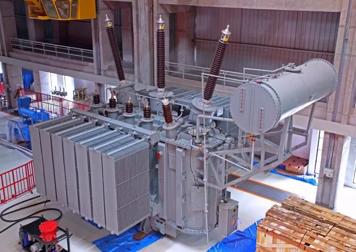
Transformer Rectifier Units (TRUs) serve as critical components in power conversion systems, efficiently transforming alternating current (AC) to direct current (DC) while maintaining voltage stability. These systems find extensive applications in industries ranging from aviation power systems to industrial electrolysis processes. Understanding the operational principles of TRUs requires examining their core components, conversion mechanisms, and system-level integration.
Core Components of a Transformer Rectifier Unit
A TRU integrates two primary functional modules: a voltage transformation section and a rectification assembly. The voltage transformation stage typically employs either a conventional iron-core transformer or an autotransformer design, which steps down high-voltage AC input to a lower voltage level suitable for rectification. The rectification assembly consists of semiconductor devices arranged in specific circuit configurations to convert the stepped-down AC into smooth DC output.
Modern TRUs often incorporate additional subsystems to enhance performance and reliability. Filter networks using capacitors and inductors suppress output ripple, while cooling mechanisms such as oil immersion or forced air circulation maintain optimal operating temperatures. Advanced units may include control circuitry for output regulation and protection features against overloads or short circuits.
Operational Principles of AC to DC Conversion
Voltage Transformation Stage
The initial AC voltage reduction occurs through electromagnetic induction within the transformer windings. When primary winding receives high-voltage AC input, it creates a fluctuating magnetic field in the core material. This alternating magnetic flux induces a proportional voltage in the secondary winding according to the turns ratio between windings. Three-phase systems commonly employ delta-wye transformer configurations to achieve both voltage transformation and electrical isolation between input and output circuits.
Transformer design considerations include core material selection to minimize hysteresis losses and winding arrangements that optimize magnetic coupling efficiency. The transformed low-voltage AC output then feeds into the rectification stage for current conversion.
Rectification Process Fundamentals
Rectification converts bidirectional AC into unidirectional DC through strategic arrangement of semiconductor devices. In three-phase systems, six or twelve diode configurations create sequential current paths that follow the highest instantaneous voltage phase. As each phase voltage peaks, corresponding diodes become forward-biased, allowing current flow while other diodes block reverse current. This switching action produces a pulsating DC waveform composed of overlapping phase voltage segments.
The rectification topology significantly influences system performance. Six-pulse rectifiers generate characteristic ripple frequencies six times the input frequency, while twelve-pulse systems using phase-shifted transformers produce smoother output with twelve ripple cycles per input period. High-power applications may employ active rectification with controlled semiconductor devices like IGBTs or thyristors for precise output regulation.
System Integration and Performance Optimization
Output Filtering and Ripple Reduction
Pulsating DC from the rectifier requires filtering to achieve stable voltage suitable for sensitive loads. Multi-stage LC filter networks attenuate ripple components by combining the energy storage properties of capacitors with the current smoothing effect of inductors. The filter design must balance ripple reduction against system response time, as excessive capacitance can slow voltage regulation during load transients.
Electrolytic capacitors provide high capacitance values in compact packages but require derating for reliability in high-temperature environments. Modern systems may incorporate active filtering techniques using feedback-controlled switching converters to dynamically cancel ripple components.
Voltage Regulation and Control Systems
Closed-loop control mechanisms maintain consistent DC output despite input voltage fluctuations or load variations. Voltage feedback networks compare actual output with reference values, adjusting transformer tap positions or semiconductor conduction angles to compensate for deviations. Digital signal processors in advanced TRUs implement sophisticated control algorithms that optimize efficiency across varying operating conditions.
Protective features form an integral part of TRU design. Current-limiting circuits prevent damage during short-circuit events, while temperature sensors initiate cooling system activation or load reduction when critical thresholds are exceeded. Ground fault detection systems enhance safety in high-current applications by identifying insulation breakdowns before they escalate.
Specialized Applications and Industry-Specific Designs
Aviation Power Systems
Aircraft TRUs convert three-phase 115V AC at 400Hz frequency to 28V DC for avionics and onboard systems. These units prioritize weight reduction through compact transformer designs and high-frequency operation. Redundant parallel TRU configurations ensure continuous power availability during single-unit failures, with automatic bus transfer switches maintaining uninterrupted supply.
Industrial Electrolysis Plants
High-current TRUs for electrochemical processes employ water-cooled rectifiers capable of delivering thousands of amperes at precisely controlled voltages. Multiple rectifier units often operate in parallel with current-balancing circuits to distribute load evenly. Specialized designs incorporate harmonic mitigation features to maintain power quality and comply with grid interconnection standards.
Conclusion
Wide-bandgap semiconductor materials like silicon carbide and gallium nitride are revolutionizing TRU design by enabling higher switching frequencies and reduced energy losses. These advancements permit more compact filter components and improved system efficiency. Digital twin technology allows predictive maintenance through real-time performance monitoring and trend analysis, potentially extending equipment service life.
Modern TRUs increasingly incorporate smart grid compatibility features, including bidirectional power flow capability for energy storage integration. These developments position transformer rectifier technology as a key enabler for renewable energy systems and electrified industrial processes.
The continuous evolution of TRU technology reflects the growing demand for efficient, reliable power conversion across diverse applications. From legacy diode bridges to sophisticated active rectification systems, these units remain indispensable in bridging the gap between AC distribution networks and DC-powered equipment. Future innovations will likely focus on further improving power density, efficiency, and intelligent control capabilities to meet the challenges of next-generation power systems.
Related Topics:

